

Literature-based case study | side-scan sonar range shadow detection. Should a survey team simply increase SSS range to cover more area when searching for small objects?
The practical question
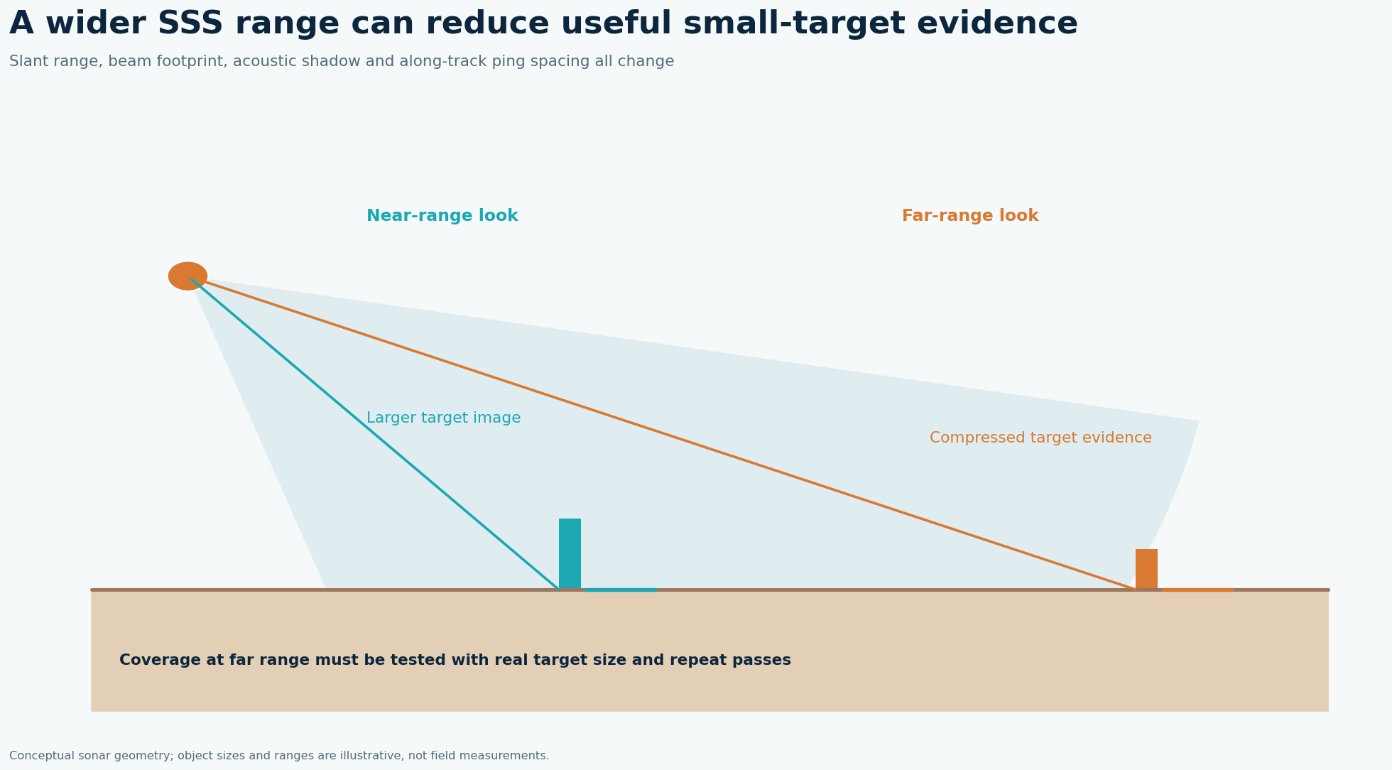
More swath per line reduces survey time, but the object spans fewer pixels in the display and along-track spacing can worsen at speed. The highlight and shadow are controlled by target height, fish altitude, look angle, range and seabed slope. A contact may disappear in a mosaic because an unfavorable pass puts its shadow into a weak-return zone or because heavy processing normalizes it away.
What the published data actually say
A field study of six wrecks in the Polish Baltic surveyed at 2–4 knots with side-scan operating ranges between 20 and 75 m while examining resolution and acoustic shadows. Source: The Impact of Side-Scan Sonar Resolution and Acoustic Shadow Phenomenon, Remote Sensing 2023. These are findings from that location and acquisition setup, not a GeoSubsea project or a universal equipment specification.
A defensible field-to-report solution
Define the minimum object size and detection requirement before line spacing. Set range and speed together with ping rate so that along-track sample spacing resolves the target; calculate ground range from slant range and measured fish altitude. Fly reciprocal or offset lines over a representative known object at two ranges. Compare raw waterfalls at the same pixel scale, document shadow length and target contrast, and choose a configuration that preserves both coverage and interpretability. Keep a near-nadir policy and overlap adjacent lines to cover the blind strip.
Worked decision example
The published 20–75 m ranges and 2–4 knot speeds are examples of field settings, not a universal optimum. Doubling range from 25 to 50 m approximately doubles nominal swath width at fixed geometry, but it does not double detection confidence; the effective insonification and image sampling must be tested against the target.
What to record in the field
Plan the survey backward from the smallest object that must be found. Estimate along-track ping spacing from speed and ping rate and compare it with the expected highlight and shadow footprint. Check across-track sample scale at both near and far range; the far edge can look quite different from the high-resolution central strip. Run a short trial line over an identifiable object at the proposed range and altitude, then another from the opposite heading. Store the raw waterfall as well as a normalized mosaic, because gain correction may hide a faint shadow.
How to make the engineering decision
The Polish six-wreck study used 20–75 m ranges and 2–4 knots, settings selected for its own targets and operating context. For smaller debris, directly test whether the shadow is visible at the farthest required range. A clean-looking image with no object is only a negative detection when the target size, aspect, blind zone and line overlap meet the survey's detection objective. In the report, draw the nadir gap and any unensonified strip, and distinguish verified clear coverage from areas where geometry prevents a reliable statement.
QC gates before accepting the interpretation
Create a contact-detection trial table by target size, range, altitude and pass direction. Inspect raw and normalized images; investigate missing shadows and blind-zone gaps before accepting a clean-looking mosaic.
Limits and next action
The six-wreck study concerns large archaeological objects; scale its geometric lessons cautiously to small boulders, debris or UXO. For a project-specific decision, identify the required engineering tolerance, review the raw survey evidence and agree the validation method before acquisition or reprocessing.
Applied decision scenario
Suppose a 50 m range mosaic shows a target on one line and no counterpart on its neighbor. Before deleting the contact, map each line’s actual insonified footprint, nadir gap, far-range resolution and aspect. The neighbor may never have observed the target at a usable geometry. Return across the contact with a shorter range or reversed heading, holding speed and altitude stable, then compare the raw waterfalls. Report a confirmed target, a disproven artifact or an unresolved contact with the underlying trial images. A blank pixel patch is not equivalent to demonstrated object-free seabed.
Questions to resolve before sign-off
How much line overlap is enough? Specify it using the usable footprint after accounting for nadir, fish altitude, far-range detectability and navigation uncertainty. Adjacent nominal swaths that barely touch may leave a practical gap for the smallest specified object. Confirm a spatial footprint map from accepted pings rather than planned line spacing alone. Why run a reciprocal pass? Shadow geometry changes with look direction and can separate a real target from texture or an artifact. Compare the contact in both raw waterfalls. A non-detection on one pass is meaningful only if the target location was insonified with adequate range and resolution. Record those conditions with every contact for audit.
Related geophysical services
GeoSubsea supports integrated side-scan sonar, sub-bottom profiler, multibeam and high-resolution 2D seismic processing, survey QC and interpretation. For a defensible site-specific assessment, start with the survey objective, raw data, positioning records and ground truth.
Explore GeoSubsea services · More case studies
Primary reference
The Impact of Side-Scan Sonar Resolution and Acoustic Shadow Phenomenon, Remote Sensing 2023. The figures above are original editorial illustrations; they do not reproduce source figures.
Leave a Reply