

Literature-based case study | 2DHR seismic time depth conversion. Can a 20 ms two-way-time interval be called a fixed burial depth without a local velocity tie?
The practical question
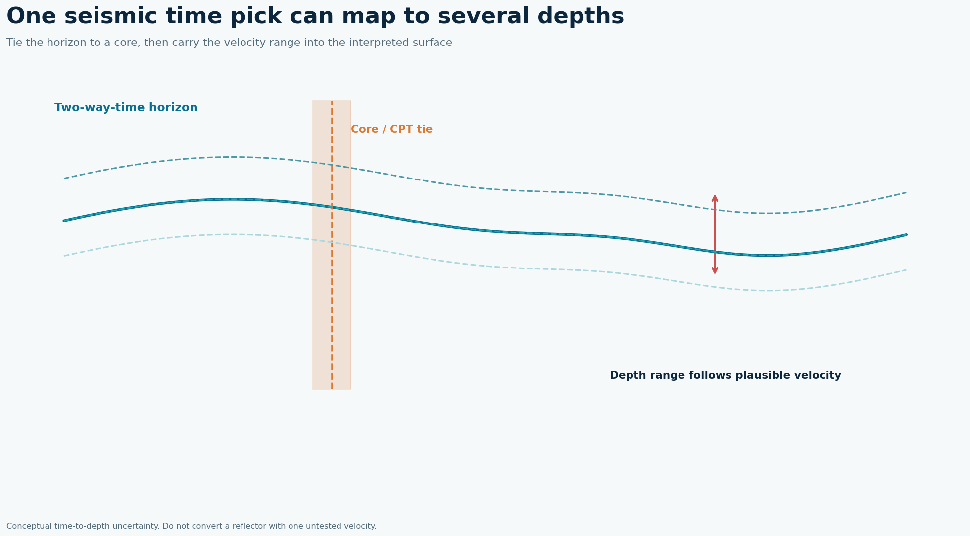
The profiler measures travel time, not sediment thickness. A constant water velocity applied to every unit assumes away compaction and lithology. In shallow engineering intervals, a small depth bias can change foundation embedment, trenchability or sediment-volume estimates. Cores also carry depth and lateral-correlation uncertainty: a core marker may not coincide exactly with the acoustic phase selected as a horizon.
What the published data actually say
USGS compared high-resolution single-channel seismic horizon times with sediment-core stratigraphic marker depths. Reported interval velocity estimates ranged from 1,161 to 2,471 m/s in its correlation analysis. Source: USGS Scientific Investigations Report 2025–5100, shallow geologic framework of Mississippi Sound. These are findings from that location and acquisition setup, not a GeoSubsea project or a universal equipment specification.
A defensible field-to-report solution
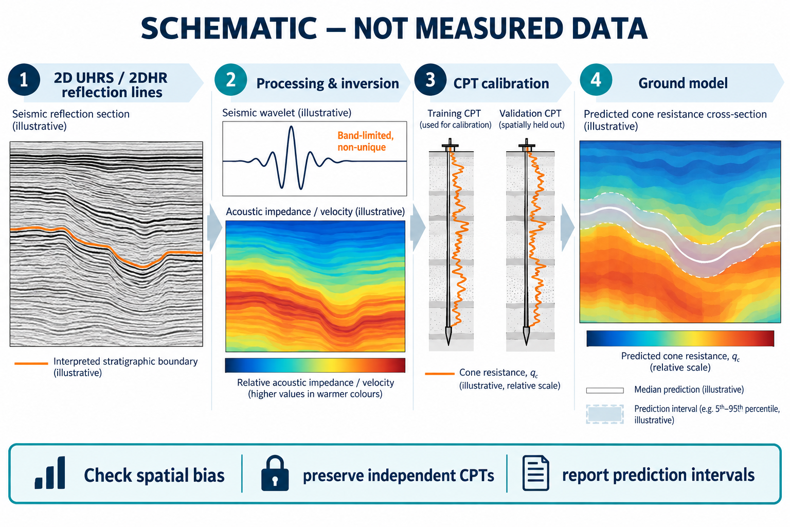
First calibrate navigation, latency and seabed time. Pick continuous horizons in two-way travel time and document polarity, pick convention and confidence. Bring cores or CPT logs into the same vertical reference and use distinct, traceable markers rather than forcing every reflector to a lithologic boundary. Compute interval velocities from two or more tied time-depth markers where possible; test plausible ranges elsewhere. Convert each horizon using piecewise velocity, then map a low, preferred and high depth surface. Recheck at crossing seismic lines.
Worked decision example
For an illustrative 20 ms two-way-time interval, depth is 11.61 m at 1,161 m/s and 24.71 m at 2,471 m/s. Those velocities span the USGS reported estimates, but the resulting range is a sensitivity calculation, not the actual depth uncertainty at any single USGS site. A core tie and appropriate interval velocity are needed to narrow it.
What to record in the field
Build a tie table with core identifier, position, seabed datum, marker depth below seabed, picked two-way travel time and the seismic event's interpretation confidence. A core sampled away from the seismic line must have its lateral separation recorded; do not silently force a marker into an adjacent reflector. Where two markers bracket an interval, estimate interval velocity from depth change divided by half the two-way-time change. If the tie is sparse, explicitly compare a range of plausible models and record the resulting depths on the interpreted profile.
How to make the engineering decision
A depth map needs an uncertainty map alongside it. Trace pick errors, velocity uncertainty, datum uncertainty and interpolation uncertainty separately so a user can see which new observation would narrow the range. The USGS Mississippi Sound analysis illustrates empirical velocity estimation using high-resolution profiles and cores; its wide reported interval range cautions against a universal constant. When a required burial margin is smaller than the unresolved depth range, commission a targeted core or in-situ velocity measurement before declaring the reflector an engineering boundary.
QC gates before accepting the interpretation
Deliver the original time section, tie table, velocity calculation, uncertainty range and depth section together. Flag extrapolated intervals beyond the last core and avoid reporting centimetre-level depths from unconstrained velocities.
Limits and next action
The source velocity endpoints come from a particular correlation analysis and should not become a default velocity model for another project. For a project-specific decision, identify the required engineering tolerance, review the raw survey evidence and agree the validation method before acquisition or reprocessing.
Applied decision scenario
Suppose a 20 ms reflector interval appears under two alternative sediment velocities that give depths of about 12 m and 25 m. If a proposed trench reaches 10 m, both models may lead to the same clearance judgment; if it reaches 18 m, the model choice is decisive. This is an illustrative design comparison, not the Mississippi Sound result. Choose the next core or in-situ velocity test where the two depth scenarios diverge and the engineering decision changes. Preserve the original two-way-time pick so the model can be revised without redrawing an apparent geological boundary.
Questions to resolve before sign-off
Which velocity applies between cores? Use an interval velocity supported by paired time and depth markers if both ties are secure. Otherwise bracket plausible models and report sensitivity. Do not call a water-column velocity a measured sediment velocity because it produces a smooth section. Record marker mismatch, core penetration uncertainty and lateral offset. How should a client use the depth range? Compare low and high depth surfaces with trench or foundation depth. If all scenarios lead to the same design choice, more velocity work may add little. If the choice reverses within the range, commission a targeted tie or in-situ measurement. That puts ground truth where it changes the engineering answer.
Related geophysical services
GeoSubsea supports integrated side-scan sonar, sub-bottom profiler, multibeam and high-resolution 2D seismic processing, survey QC and interpretation. For a defensible site-specific assessment, start with the survey objective, raw data, positioning records and ground truth.
Explore GeoSubsea services · More case studies
Primary reference
USGS Scientific Investigations Report 2025–5100, shallow geologic framework of Mississippi Sound. The figures above are original editorial illustrations; they do not reproduce source figures.
Leave a Reply