

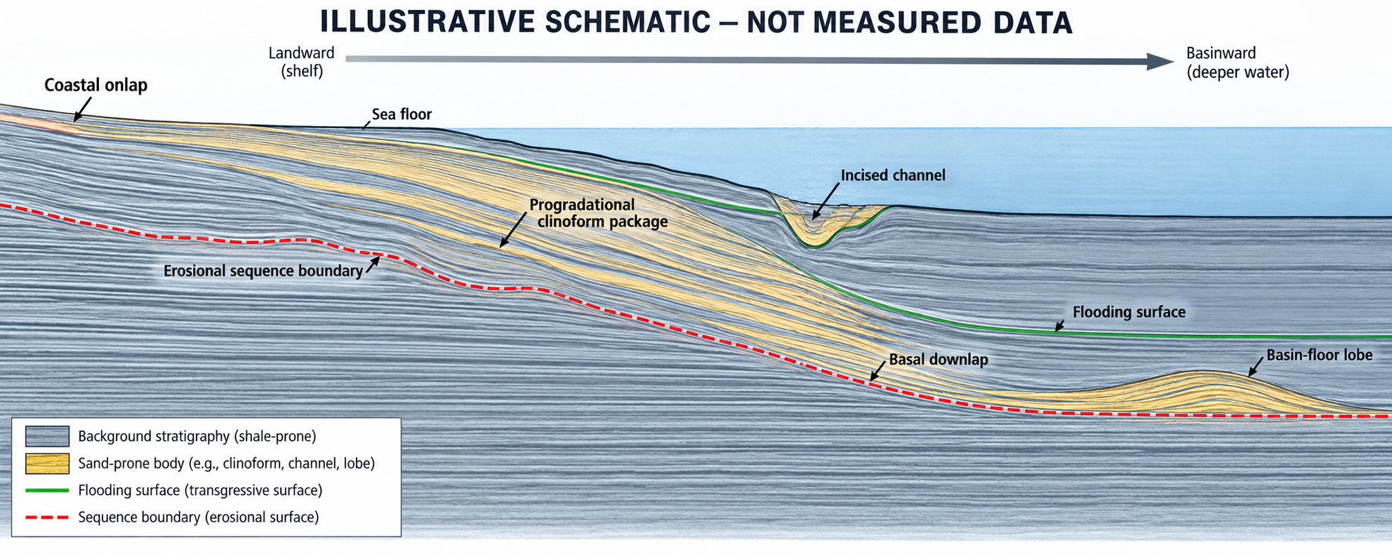
Case-study note: the supplied graphic is a conceptual seismic-stratigraphy illustration. It contains no acquired survey data, well ties, coordinates or measured geological result. The “case” below shows how a team could test its interpretation when building an offshore wind or cable-route ground model.
A line that appears to tell a story
Picture a dip line running from a shallow shelf toward a deeper basin. Near the shelf edge, reflections step basinward in a broad wedge. Some terminate against a green, nearly continuous surface; others descend to meet it. A red, irregular boundary cuts older reflectors below. Farther basinward, a small channel incision feeds a mound-shaped body. On the shelf, a separate narrow channel has inclined internal reflections. The geometry invites a narrative: shoreline migration, delta growth, erosion, and sediment delivery to a basin-floor lobe.
That narrative is useful only if its confidence is calibrated. Seismic reflections map contrasts in acoustic impedance, shaped by lithology, porosity, fluid, bed thickness, tuning, wavelet and processing. They do not label sand, mud, age or engineering properties by themselves. The first disciplined distinction is therefore between what the data show—reflection terminations, continuity, amplitude and geometry—and what the interpreter infers about depositional process.
Reading the geometry, not over-reading the label
The shelf-margin package is consistent with progradation: successive clinoforms advance basinward, while their basal reflections downlap onto a lower surface. Coastal onlap landward and truncation below may support a sequence boundary, but neither feature alone proves a particular sea-level event. A candidate maximum flooding surface may provide a useful regional datum where it can be traced and independently correlated; a single green-looking reflector is not enough. The supplied figure correctly emphasizes that reflection patterns are non-unique and require well, core, biostratigraphic and regional context.
The three plan-view cartoons sharpen the ambiguity. A sinuous channel with point-bar-like lateral accretion could fit a meandering fluvial system. A branching feeder and lobate mouth-bar pattern could fit a delta. A leveed channel feeding compensationally stacked lobes could fit a deep-marine system. In a two-dimensional section, each may collapse into a channel-shaped cut and a wedge or mound. A dip line can suggest migration or progradation; it cannot establish a three-dimensional planform that was never imaged.
Published seismic-stratigraphic guidance treats reflection terminations and seismic facies as a framework for identifying discontinuities and organizing depositional history, while stressing that setting and regional geology matter. A 2023 Niger Delta study demonstrates how 3D geometry, internal reflection character and structural context can constrain submarine channel pathways and sedimentary architecture. That is a published natural example, not evidence about this schematic or a GeoSubsea project.
From interpretation to a ground-model question
For offshore wind and subsea cable work, the practical question is not “Is this definitely a delta?” It is “Where could the interpreted architecture change the conditions we must verify?” A buried channel may juxtapose erosional contacts and fill with different stiffness or grain-size distributions. A shelf-margin wedge may contain laterally variable beds. A basin-floor lobe may indicate a mounded stratigraphic body, but its reflection amplitude cannot be translated directly into sediment strength or cable burial performance.
Those are hypotheses for survey design, not geotechnical conclusions. The schematic gives no scale, velocity model, age control or site-specific calibration. Its time axis is two-way travel time, not depth; converting it requires an appropriate velocity model. The drawn vertical exaggeration also makes slopes and relief visually stronger than they may be in reality. Do not turn the apparent channel depth, lobe thickness or clinoform angle into a design measurement.
A QC workflow that can falsify the story
- Check the seismic foundation. Confirm navigation, line orientation, datum, tide/heave corrections where relevant, source and receiver geometry, bandwidth, phase, polarity, processing sequence and vertical resolution. Review raw or minimally processed gathers and adjacent lines for multiples, ringing, footprint, migration smiles and acquisition gaps that could mimic terminations.
- Map observations before facies names. Track candidate horizons and mark onlap, downlap, truncation and reflector continuity separately. Record confidence and alternative picks. Test whether a boundary persists across intersecting lines and whether apparent truncation could instead be faulting, tuning, an unconformity outside the section, or processing damage.
- Test dimensionality. Use a 3D volume, crossing profiles, or targeted additional lines to see whether a channel is sinuous, branching or confined, and whether lobes compensate laterally. If only sparse 2DHR lines exist, show the interpolation uncertainty explicitly rather than drawing a continuous channel between crossings as fact.
- Calibrate, then update the model. Tie reflectors to boreholes, CPTs, cores, shallow geophysics and biostratigraphy where available. Compare predicted boundaries with actual logs and sample descriptions. Use MBES morphology and SBP/2DHR shallow imaging as complementary evidence, while respecting their different resolution and penetration. A mismatch is a reason to revisit the interpretation, not to relabel the ground data.
- Translate uncertainty into action. Place ground-truth points near channel margins, erosional surfaces and interpreted facies transitions, where a route or foundation decision is sensitive to the boundary. Preserve alternative geological models and confidence polygons in the report; identify what new line, core or CPT would discriminate between them.
What a defensible case-study conclusion sounds like
A careful report might say: “The line contains a basinward-prograding reflection package above a candidate erosional surface, with a channel-shaped incision and a mounded basinward body. These geometries are compatible with shelf-margin progradation and channel–lobe sedimentation, but fluvial or deltaic alternatives cannot be excluded from the available 2D section. Lithology and engineering properties remain uncalibrated.” That wording is vivid enough to guide the next survey and cautious enough to survive review.
Seismic stratigraphy is most powerful when it narrows the questions asked of the ground investigation. Onlap, downlap, truncation and clinoform geometry can reveal where architecture changes; calibration and uncertainty decide what those changes mean for a cable corridor or turbine location. The goal is not a beautiful depositional story. It is a testable subsurface model whose weak links are visible before they become construction surprises.
References
- SEPM Strata, Seismic Interpretation: reflection terminations and seismic facies.
- Pizzi et al. (2023), Structural controls on the pathways and sedimentary architecture of submarine channels: New constraints from the Niger Delta, Basin Research.
- SLB Energy Glossary, Maximum flooding surface.
Leave a Reply