

Why this matters for route screening
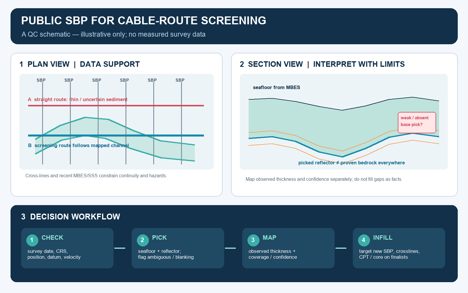
A cable route can look attractive on a bathymetric map and still have too little penetrable sediment for the intended installation method. Multibeam echosounder (MBES) describes seabed shape; side-scan sonar (SSS) helps map texture and objects; a sub-bottom profiler (SBP) adds evidence about shallow buried interfaces. Combining these layers can improve early route comparisons, but an interpolated sediment-thickness map is not a burial guarantee.
A 2026 peer-reviewed study by Walsh, Holloway and Lim is a useful example. The authors integrated public geospatial layers with SBP for offshore wind export-cable route screening in Ireland. They interpreted 506 pinger-profiler lines from seven INFOMAR surveys acquired between 2007 and 2016, and used the results to refine routes across selected areas. Their mapped upper sediment units and buried channels showed how subsurface geometry can change the relative attractiveness of a route that looks similar at the seabed. The study is a published journal article, not a preprint. Its result is a feasibility workflow for those study areas, not validation of a final engineering route elsewhere.
What an SBP thickness surface actually represents
An SBP record is a two-way travel-time image. To convert a picked reflector into depth below seabed, the interpreter needs a stated acoustic-velocity model and a consistent seabed pick. The strongest continuous reflector is not automatically bedrock: it may represent a sediment boundary, till, a buried channel surface, or an interface below which the instrument no longer resolves geology. The 2026 study explicitly notes that its interpolated values describe the maximum identifiable sedimentary-unit thickness, not a proven depth to bedrock. It also describes one basal interpretation as bedrock or possibly glacial till.
This distinction changes the decision. “At least 2 m of sediment is mapped here” can mean that a reflector was interpreted at that thickness on nearby lines and interpolated between them. It does not establish that the material is homogeneous, trenchable, thermally suitable, or present continuously along the cable centreline. Nor does an SBP alone determine the required burial depth, which depends on project design, installation method, seabed mobility, external threats and applicable engineering requirements.
QC the source data before interpolation
1. Establish provenance and comparability. Build a line register with survey date, vessel and sensor, source type and frequency, towbody or transducer arrangement, line name, navigation source, coordinate reference system, vertical datum, time basis, processing history and available ground truth. The INFOMAR viewer provides access to sub-bottom SEG-Y and a user guide; obtain the original trace data and metadata where possible, rather than relying only on a composite image. A mosaic assembled from surveys made years apart can contain real geology, acquisition differences, or both.
Check whether line navigation refers to the vessel, a towed fish, or a fixed hull-mounted transducer. Review layback, antenna-to-sensor offsets, clock synchronization and gaps in position updates. A lateral mismatch between the acoustic profile and MBES seabed can create a false thickness change or shift a channel edge. Record uncertainty instead of forcing dissimilar vintages into apparent agreement.
2. Re-pick the seabed and candidate horizons consistently. Confirm the seafloor time break across the full line, flag ringing, multiples, water-column noise, bubble attenuation and areas of weak penetration. Track each reflector’s continuity and character; mark alternative picks where the geology is ambiguous. Convert time to depth using a justified velocity assumption, retain the original time picks, and record whether thickness is measured vertically or normal to the seabed. Where a pinger profile loses the basal return, classify the base as unresolved or deeper than observed. Do not draw a confident bedrock surface through acoustic blanking.
3. Keep observation separate from interpolation. Store picked thickness at line positions with a confidence class and the distance to supporting lines. Make a map of data coverage alongside the thickness surface. Interpolate only within a defensible survey footprint; mask broad gaps and extrapolated margins. Test whether the preferred route survives reasonable changes in grid cell size, interpolation method and maximum search distance. A smooth raster can conceal sparse control. The 2026 paper used a 100 m output grid and states that this scale is suited to feasibility planning; it calls for more detailed seabed mapping on shortlisted routes.
Use integrated evidence to decide where to survey
Compare the interpreted subsurface with recent MBES morphology and SSS contacts. A paleochannel inferred from SBP should be checked against cross-lines and seabed context; a channel may contain thick sediment but also mobile or fine-grained fill. Sediment grabs or cores can ground-truth surficial acoustic facies, while cone penetration tests (CPTs) and boreholes on route candidates test strength, stratigraphy and installation behaviour. These measurements answer different questions. A grab does not verify a reflector tens of metres below seabed, and a CPT is local rather than a continuous map.
Use a decision table rather than a single “best route” raster: show route length and constraints, observed sediment thickness, unresolved areas, survey age, confidence, and the evidence still needed. Run alternative weightings for cost, environment and constructability. If route ranking changes when a plausible boundary or interpolation choice changes, that is a trigger for targeted infill, not a reason to hide the uncertainty.
A practical screening gate
Public SBP data are most valuable when they narrow a large search area and guide new acquisition. Before treating a route as a preferred corridor, verify that the data vintage is fit for current seabed conditions, the interpreted base is appropriate to the project question, and the corridor has adequate cross-line control. Then plan new high-resolution SBP or 2DHR lines, MBES and SSS coverage, and geotechnical sampling around the uncertainties that could change the decision. The current IHO S-44 edition provides a hydrographic survey-quality framework, but it is principally a standard for hydrographic surveys; it does not replace project-specific geophysical, geotechnical or cable-burial criteria.
The sound conclusion from an SBP route screen is therefore not “this route is safe to bury.” It is “these alternatives have different evidence-supported subsurface conditions, and here is where additional data will most efficiently reduce uncertainty.”
References and further reading
- Walsh, K., Holloway, P. & Lim, A. (2026). Optimising submarine cable routes from offshore wind farms. Journal of Ocean Engineering and Marine Energy, 12, 971–993. Peer-reviewed open-access research.
- INFOMAR. Data and Sub-Bottom Profiler Viewer, including access to sub-bottom SEG-Y data and the user guide.
- International Hydrographic Organization. S-44, Standards for Hydrographic Surveys, Edition 6.2.0 (October 2024).
Leave a Reply