

Literature-based case study | MBES sound speed outer beam cupping. When adjacent MBES swaths form a shallow smile or deep frown, should the processor smooth the grid?
The practical question
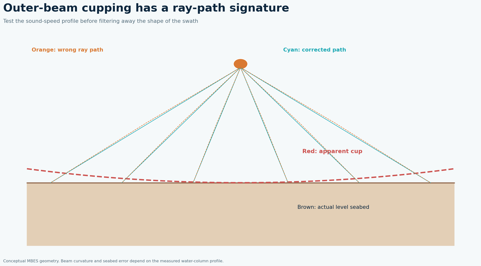
Ray tracing bends outer beams through the water column. If the applied profile no longer represents the local water mass, the across-track error often grows toward the swath edge and creates a characteristic cupping pattern. Gridding smooths the seam but does not repair the depth measurement. A surface-speed error can also affect beam steering even when the cast is otherwise plausible.
What the published data actually say
NOAA survey specifications require a sound-speed profile deep enough for the ray tracing needed to meet survey depth accuracy and explicitly identify sensor error plus spatial and temporal sound-speed variation as uncertainty sources. Source: NOAA Hydrographic Surveys Specifications and Deliverables 2019, Sound Speed Corrections for Multibeam Surveys. This is methodological guidance; a project must apply its own survey order and measured sound-speed variation.
A defensible field-to-report solution
Compare a flat seabed line and its reciprocal, stratify sounding residuals by beam angle and time, and review casts, surface sound speed, tides and motion together. Identify when and where a profile changed relative to survey lines. Reapply the best defensible profile and compare crossline residuals on the same vertical datum. If the outer angles remain unreliable, reduce usable swath width and reacquire the coverage. Set cast frequency based on observed water-mass variability rather than a fixed clock interval alone.
Worked decision example
As a transparent illustrative QC gate, a team might flag outer-beam crossline residuals exceeding its project total vertical uncertainty budget and check whether a new cast removes the angle-dependent bias. The numerical threshold must come from the project survey order, water depth and uncertainty model; NOAA’s cited passage does not prescribe one universal residual value.
What to record in the field
Plot difference from a reciprocal line against across-track beam angle and acquisition time. Sound-speed refraction tends to create a symmetric outer-angle pattern, but time-varying water masses can change its magnitude between lines. Review surface sound speed at the transducer, profile cast location and depth, vessel motion, tide and installation geometry. Re-raytrace a limited sample with the nearest valid profile before reprocessing the whole block. If the pattern persists after sound-speed correction, investigate patch-test alignment and vertical-reference issues rather than attributing every seam to water-column physics.
How to make the engineering decision
A project acceptance gate must use its applicable survey order and total propagated uncertainty. There is no universal 'one-metre outer-beam' allowance in the NOAA guidance cited here. Keep plots before and after correction at the same color scale and calculate crossline residuals on independently acquired data. If only the center beams meet the required uncertainty, reduce the accepted swath and plan infill. That is an acquisition decision with cost implications, and it should be made while the vessel can still return to the site.
QC gates before accepting the interpretation
Archive casts with time and position, beam-angle residual plots, crossline statistics and the accepted versus rejected beam-angle range. Review shallow and deep portions separately; avoid claiming an improvement from a prettier grid without independent crossline evidence.
Limits and next action
The diagnostic shape is suggestive, not unique: wrong lever arms, heave, tide or alignment can mimic parts of the pattern and must be excluded. For a project-specific decision, identify the required engineering tolerance, review the raw survey evidence and agree the validation method before acquisition or reprocessing.
Applied decision scenario
Suppose overlap surfaces show outer-beam depth residuals increasing away from nadir, with the pattern stronger after a warm surface layer develops. Plot those residuals by angle and time, compare the casts around the water-mass change and re-raytrace a small test block. If the bias improves on independent crosslines, apply and document the correction. If it remains, inspect motion and alignment before acquiring infill. The conceptual figure indicates a shape to investigate, not an acceptance curve; use the project total propagated uncertainty and coverage requirements for the final gate.
Questions to resolve before sign-off
Can a new sound-speed cast repair old swaths? Possibly, if it represents the water column at the time and place of those pings. A cast taken after a front passes may worsen earlier lines. Compare time, location and independent crossline residuals before re-raytracing. What if the crossline still disagrees? Stratify error by angle, heading and time. Symmetric outer-angle error supports refraction; heading-dependent tilt may point to roll alignment; uniform vertical offset invites a datum or tide check. Test each explanation with plots and metadata. Where outer beams exceed the uncertainty budget, reject them and acquire infill instead of blending a biased surface into the grid.
Related geophysical services
GeoSubsea supports integrated side-scan sonar, sub-bottom profiler, multibeam and high-resolution 2D seismic processing, survey QC and interpretation. For a defensible site-specific assessment, start with the survey objective, raw data, positioning records and ground truth.
Explore GeoSubsea services · More case studies
Primary reference
NOAA Hydrographic Surveys Specifications and Deliverables 2019, Sound Speed Corrections for Multibeam Surveys. The figures above are original editorial illustrations; they do not reproduce source figures.
Leave a Reply