

Literature-based case study | side-scan sonar layback accuracy. Can an apparent cable-route obstruction be cleared using the vessel GPS coordinate alone?
The practical question
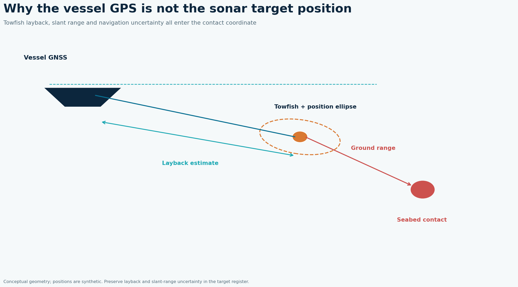
A target picked from a side-scan mosaic inherits the uncertainty of the towfish, not merely that of the antenna. A fixed layback assumes the fish follows the vessel at a predictable offset. Turns, cross-currents, varying cable scope and changing altitude violate that assumption. A sharp-looking contact can therefore be mapped precisely in pixels yet inaccurately in geographic space.
What the published data actually say
The USGS reported a conservative ±10 m positional accuracy for a towed Klein 3000 survey even though the vessel RTK-GPS position was likely better than 1 m. Its Vineyard Sound dataset likewise conservatively estimated position within 10 m after allowing for fish movement, cable movement and RTK dropouts. Source: USGS, Duxbury–Hull sidescan tracklines and Vineyard Sound backscatter metadata. These are findings from that location and acquisition setup, not a GeoSubsea project or a universal equipment specification.
A defensible field-to-report solution
Start the position chain at the antenna and write down lever arms to the tow point. Synchronize navigation and ping clocks, then record measured cable payout, fish depth, altitude and vessel speed for each line. Reprocess a representative subset with revised layback; compare contact coordinates on reciprocal or crossing lines. For critical targets, acquire an independent acoustic fish position or a second line with a different geometry, and verify the result with MBES, ROV or another suitable method. Attach an uncertainty envelope to each contact rather than publishing a single false-precision coordinate.
Worked decision example
If two independent passes put one contact 8 m apart, that disagreement is an observed repeatability diagnostic, not proof that the true position lies halfway between them. A nominal ±10 m survey uncertainty is already the scale of a narrow cable corridor. Define a clearance buffer from the project hazard requirement, the target dimensions and the validated position uncertainty; resurvey contacts whose buffer intersects the corridor.
What to record in the field
The acquisition sheet should distinguish cable paid out from horizontal layback. A cable counter measures a length along a curved cable, while the horizontal towfish offset also depends on depth, drag and current. Record the fish pressure depth and altitude at each important contact, and review turns separately from straight stable lines. If the contract calls for a target position accurate enough to support a trench avoidance decision, design at least one independent check before the vessel leaves the site. A later desktop correction cannot recreate a fish trajectory that was never measured.
How to make the engineering decision
The decision is made against a corridor, not against a single dot. Plot the detected object's estimated footprint, the route centerline, the route-width tolerance and the position uncertainty on the same map. If that uncertainty envelope intersects the route, label the contact unresolved and propose a targeted second pass or close-range verification. A seemingly clear 5 m separation cannot be treated as robust when the survey's conservative horizontal accuracy is ±10 m. Conversely, a well-tied USBL solution should be judged by its own demonstrated errors, not automatically assigned the older USGS figure.
QC gates before accepting the interpretation
Reject unreviewed target coordinates when navigation drops out, cable payout changes abruptly, fish altitude becomes unstable, or opposite-direction passes disagree beyond the project tolerance. Preserve raw pings, navigation, layback settings, target picks and reprocessed versions in the handover.
Limits and next action
The published ±10 m is specific to those USGS datasets; it is neither a universal SSS specification nor a tolerance for every cable project. For a project-specific decision, identify the required engineering tolerance, review the raw survey evidence and agree the validation method before acquisition or reprocessing.
Applied decision scenario
Suppose a planned cable centerline passes 6 m from a contact on the mosaic and the operator reports centimeter-level RTK position. The RTK precision applies to the antenna; the contact uncertainty must also include the fish trajectory and pick. Mark the contact as potentially inside the engineering corridor until a reciprocal pass or independent position fix resolves it. The deliverable should give the line and ping identifiers, the original pick, measured offsets, corrected coordinates and a reasoned buffer. A design team can then choose a route adjustment or a focused verification survey with its uncertainty visible.
Questions to resolve before sign-off
What if the opposite passes disagree but both look sharp? Sharpness measures image contrast, not georeferencing. First compare raw antenna navigation, tow point offsets, cable payout and line direction. Separate a systematic along-track shift from a cross-track shift; the former may indicate latency or layback, while the latter can indicate fish motion or heading. Do not average coordinates merely to make a neat target table. Report the spread and the reason for any chosen position.
When should the vessel return? Return while the sensor configuration and sea state can still be replicated if a critical contact’s uncertainty envelope overlaps the designed route clearance or if navigation has a prolonged dropout. A short reciprocal test around a known landmark can reveal whether the error repeats across the survey block. Preserve both the original and corrected contact lists so decisions remain auditable.
Related geophysical services
GeoSubsea supports integrated side-scan sonar, sub-bottom profiler, multibeam and high-resolution 2D seismic processing, survey QC and interpretation. For a defensible site-specific assessment, start with the survey objective, raw data, positioning records and ground truth.
Explore GeoSubsea services · More case studies
Primary reference
USGS Duxbury–Hull sidescan trackline metadata; USGS Vineyard Sound backscatter metadata. The figures above are original editorial illustrations; they do not reproduce source figures.
Leave a Reply